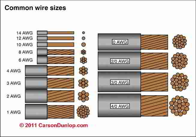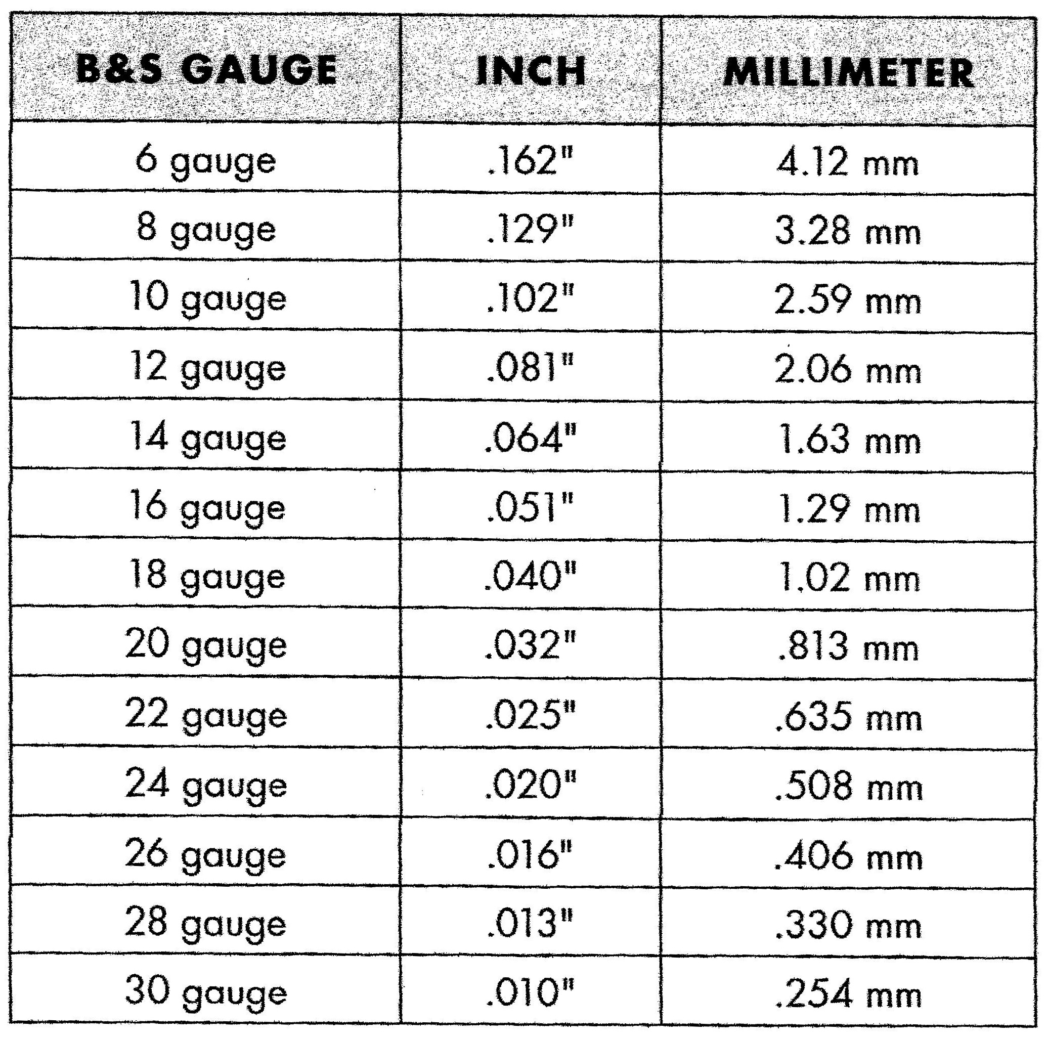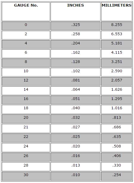


The other is the loss on the wire due to resistance. That is for the ampacity, which is only half of what drives the size of your wire. It's only a little better in a 24V system. In a 12V system, loosing 0.81V in the wire is a killer. So the total loss is actually 2 * 0.405V = 0.81V. But wait! You have current going down two wires (red and black) for that 40 feet. Now multiply that resistance times the current of 100A, and you get a loss in 40 ft of 40*0.010132 = 0.405V. Now if you look at the table above, you see that 4AWG has a nominal resistance (at 25☌) of about 0.2533 ohms per thousand feet. Based on the ampacity, you decide 4AWG should be close enough (Ampacity of 95A with 90☌ rated insulation). So let's say you have your batteries 40 feet from your inverter, and you expect a maximum current of 100A (40 feet is extreme, but stay with me). I don't remember for sure, but I thought it was NEC chapter 4 table 8 (but who knows?). For that you need to look at a different NEC table. I suppose another 150A fuse connected between the extended cable and the 3kW PSW inverter would be an easy way to eliminate that small remaining risk but if all of you think chassis wiring limits apply even to DC wires feeding inverters for continuous use, I may not bother…Ĭlick to expand.That is for the ampacity, which is only half of what drives the size of your wire.

My inverter should never draw over 130A but if it shorts and draws over 190A but under 225, that’s the potential risk I may be taking. My 3KW inverter has 90% efficiency and will be drawing 130.2A off of my battery if I let it run flat out (so fuse will not blow even at max load).Ģ/0AWG is rated for 283A when used for ‘Chassis Wiring’ so tons of headroom as long as my through-air wiring qualifies.īut 2/0AWG is only rated for 190A when used for ‘Power Transmission’ which generally means wired through conduit but also means continuous use (as should probably apply to an inverter). No safety concerns at all, but I want to wire in my 3KW PSW inverter to be used only during a power outage and have been thinking about how much risk I’d be taking by just extending a single pair of 2/0 cables. I’m using 2/0 Welder’s wire to feed 2 1kW GTIL inverters from my 24V LiFePO4 battery now (with separate runs to reduce voltage drop) protected by a 225A MEBF fuse. The fact you guys apparently consider my calculations on the conservative side is reassuring. So I guess I wouldn't go heavy on the copper with either of those.Ĭlick to expand.Absolutely correct (though since he stated he was a noob, no harm in giving him a list of other considerations to keep in mind). On the AC side, well, I guess there will be two sets of plugs, one for MSW and one for true sine wave. But the way my minivan is situated, there won't be any long runs on the DC side, partly because that's the way I prefer things. One of these days, after I add more than I might hook up the 1500W modified sine wave inverter and try running the electric kettle, and the microwave, at the same time. I admit I take care not to run them at the same time, and they don't run for more than a few minutes at a time. On the AC side, well, I'm currently using a power strip which I happened to have lying around, which might be 16AWG, with a 700W microwave and a 1000W electric kettle as the primary power consumers. Actually I am getting away with it, in testing.

Well, I only have a 2000W inverter connected so far, so maybe I will get away with it. Some of those are good answers, aren't they? Even if I am running nowhere near 1AWG, or even 2AWG, on the DC side of my setup.
#24v wire gauge chart full
So my earlier estimate was not as conservative as I thought and planning for 130A of sustained current, protected by a 160A fuse and wire sized for a full 200A (or even 205A) would be safer. My 24V 3kW inverter (WZRELB) has efficiency of 90%, so 3000W out needs 3333W in or 130A 25.6V. The battery will rarely if ever be down at 24V (at least if LiFePO4 - he did not specify which battery chemistry he has) so if we take a minimum voltage of 25.6V instead, that would bring max current down to 117A (or 183A after the two corrections) but that reminds me that I overlooked inverter efficiency (which works in the opposite direction). That is conservative but for me, at least, the one place there is little upside to pushing the limits is the highest-current path from battery to inverter. Sizing the wire 125% of the breaker size takes you to 188A (or 195A from a full 156A breaker). To avoid nuisance trips, you probably want your breaker sized at ~125% that level or ~150A. Click to expand.I figured a full 3kW supplier from a 24V battery translates to 125A.


 0 kommentar(er)
